Wimshurst Machine
The Wimshurst influence machine is an electrostatic generator, a mechanism for generating high voltages invented by British inventor James Wimshurst (1832–1903) between 1880 and 1883.
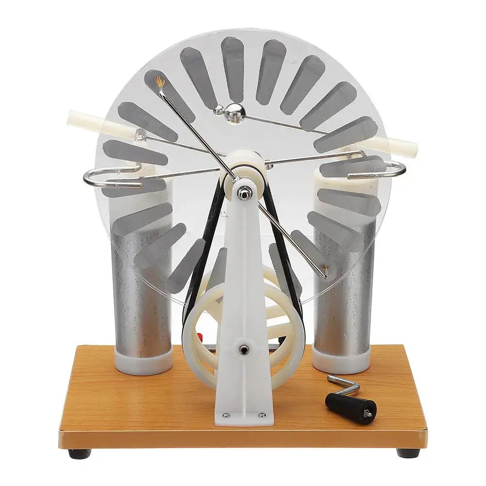
Two contra-rotating discs positioned in a vertical plane, two crossed bars with metallic brushes, and a spark gap generated by two metal spheres give it a distinctive appearance.
Components:
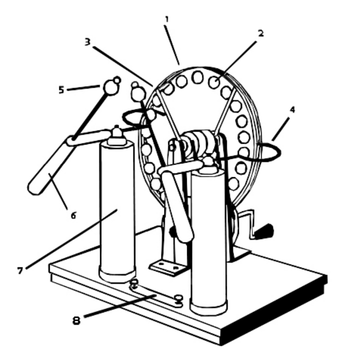
- Two Insulating Plates – These two plates are spun in opposite directions via a hand crank and a couple of pulleys (one of them twisted forming an 8 shape).
- Conducting Sections – A conducting material (often aluminum) is placed around the rim of each plate in evenly spaced intervals. Electrons from this material are physically transferred by the machine to be stored in its two Leyden jars (capacitors).
- Two Metal Rods with Brushes – These metal rods, which are positioned at a 90° angle to each other, have fine wire brushes on their ends. These brushes induce charges on the conducting sections of the opposite plate.
- Electricity Conducting Arms – These curved arms point small needles towards the spinning plates (though the needles do not come into contact with them). They serve as the point where the induced charges jump from the plates to be stored in the Leyden jars.
- Metal Discharge Balls – Discharge wands are attached to each Leyden jar. The metal balls at the end of each rod act as discharge points to form the spark gap.
- Insulating Handles – Insulating handles are important so that you can manipulate the size of the spark gap without getting shocked yourself or accidentally discharging the charge in an unintended way.
- Leyden Jars – Leyden jars are used to store electrical charges. They are covered in a conductive coating and are attached via a connector switch. Leyden jars were a percursor to modern capacitors.
- Connector – This switch allows the user to connect the conductive surfaces of the Leyden jars to each other. When the jars are connected, the outer layer of the jar becomes charged allowing the inside of jar to have a larger capacity for charge. This, in turn, creates larger, brighter, and less-frequent sparks.
Working Principle:
- To start the charging process, any tiny charge on any of the two discs is sufficient. Assume that the rear disc has a negligible net electrostatic charge. Assume that this charge is positive (red) and that the back disc ([A] lower chain) rotates counter-clockwise for clarity (right to left). As the charged sector (moving red square) rotates to the position of the brush ([Y] down arrow tip) next to the front disc ([B] upper chain near centre), it causes charge polarisation on the conducting shaft ([Y-Y1] upper horizontal black line) holding the brush, attracting negative (green) charge to the near side ([Y] upper square becoming green), and positive (red) charge to the far side (across the disc, 180 degrees away) ([Y1] upper square becoming red).
- The polarised charges on the shaft attach to the nearest sectors on disc B, resulting in a negative charge on B [Y] that is closer to the initial positive charge on A, and a positive charge on the other side of B [Y1]. The positive (red) charge on A (lower chain) is repelled by a positive (red) charge on B ([Z] higher chain) approaching after another 45° rotation ([Z] near lower chain middle). The first collecting comb ([Z] arrow-tipped lines to triangles) encountered permits both positive (red) and negative (black) charges to accumulate in the Leyden jar anode (red triangle) attracted to the Leyden jar cathode (green triangle). When a spark (yellow zigzag) discharges the Leyden jar, the charge completes the cycle across the discs (red and green triangles).
- The charges that have been produced on B line up with the brushes next to disc A [X, X1] as B rotates 90° clockwise (left to right). The charges on B cause the shaft of the A-brushes to polarise in the opposite direction, and the polarisation of the shaft is transferred to the disc. The charges from Disc B are collected by the charge-collection combs closest to it as it rotates.
- Similar to the description two paragraphs above, disc A spins 90 degrees so that its charges line up with the brush of disc B [Y, Y1], where an opposite charge-polarization is produced on the B conducting shaft and the nearest sectors of B.
- Each charge polarisation on A induces polarisation on B, which induces polarisation on A, and so on. Until the conducting shaft’s finite capacitance balances the “impact” of nearby attractive sectors, exponentially bigger charges are induced. Combs collect all of the induced positive and negative charges to charge the Leyden jars, which are electrical charge-storage devices comparable to capacitors. The electrical output is powered by the mechanical energy necessary to separate the opposing charges on adjacent sectors.
Instructions:
- As you turn the handle, you’ll notice sparks between the electrodes’ metal discharge balls.
- Slowly raise the spark gap distance and watch as the sparks get longer and less frequent.
- Insert a piece of paper into the spark gap while spinning the handle. When held up to the light, little holes in the paper will be seen. The charred borders around the small micro-holes can be seen under a microscope.
Links:
MIT Physics Demo — The Wimshurst Machinehttps://static.fishersci.eu/content/dam/fishersci/en_US/documents/programs/education/technical-documents/data-sheets/wimshurst-machine-data-sheet.pdf